Before the iron
The pack is about 18 to 21 volts. A strand from B+ to B- welds and can start a fire. Unplug the USB lead. Take the shoe off the pack. Solder on the bare boards.
The yellow jumper on the blue board stays on 3V3. The 5V pad is not used.
Yellow is the only lead that may touch B+. It lands on HV of the red board. It never lands on the FT232.
Hold J2 low before the shoe touches the pack. If J2 sits high while you plug in, the pack counts a dumb charge. Run the idle step in the public reader first, then seat the shoe, B- first.
Your parts
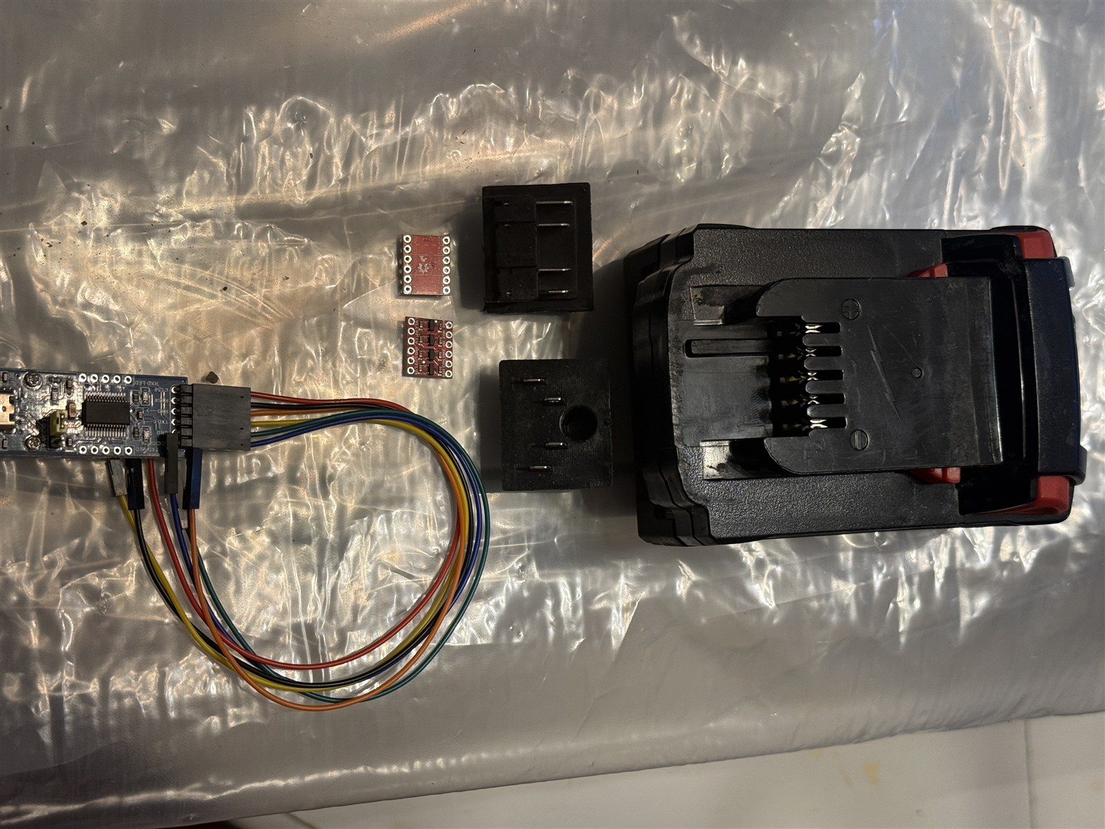
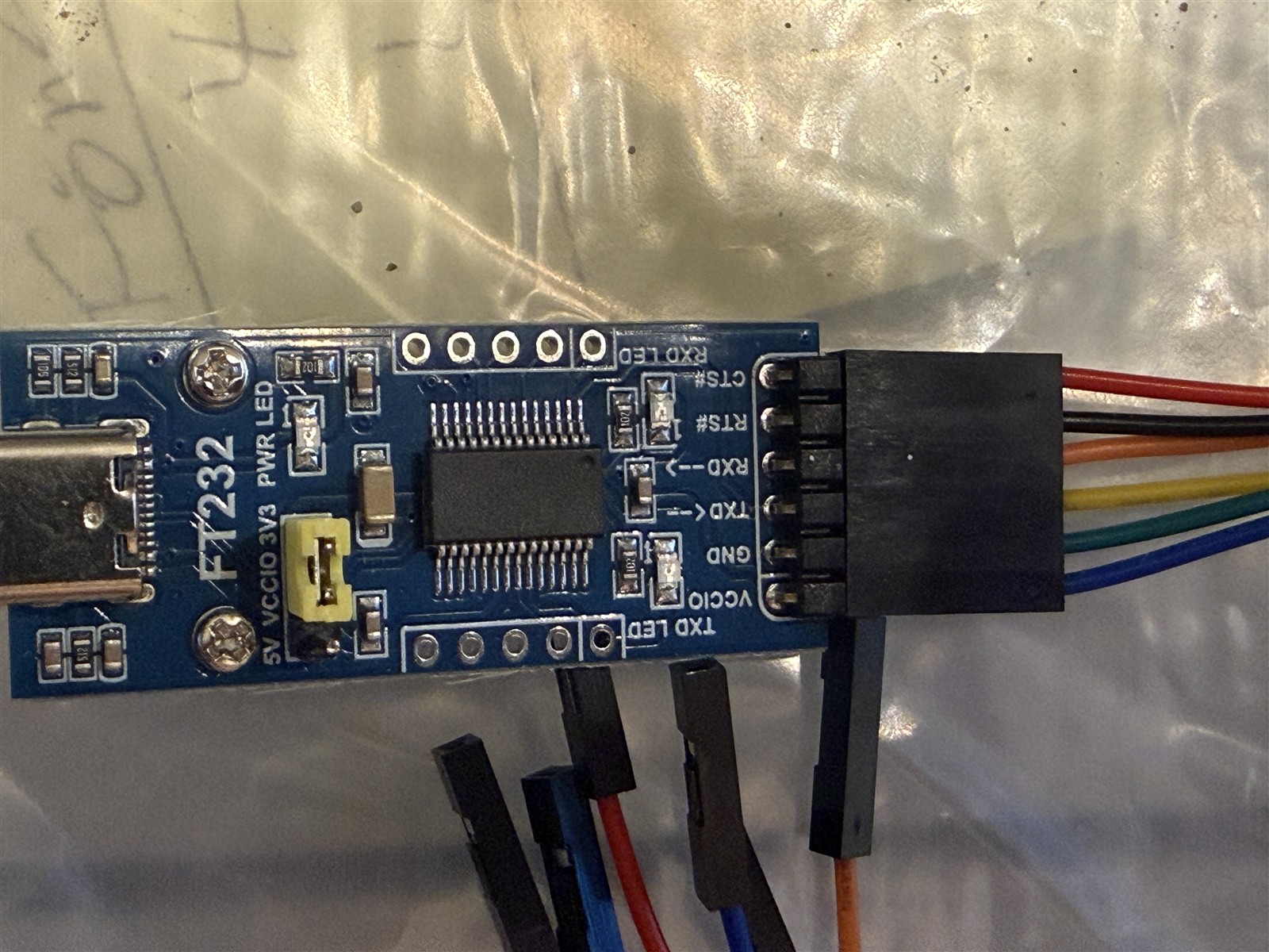
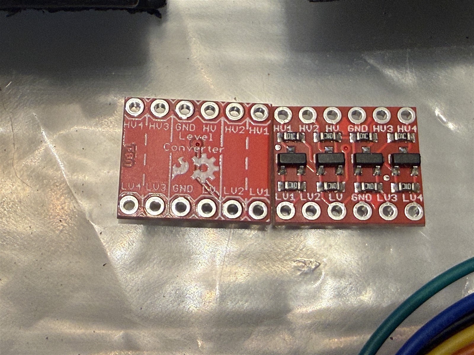
The six leads
Follow the silk, not the rainbow already in the grey shell. Trace each new lead to the printed name.
| Lead | From | To |
|---|---|---|
| Black | FT232 pad marked GND | Red board GND, and the pack blade B- |
| Red | FT232 pad marked VCC or VCCIO, on the 3V3 side of the jumper | Red board pad marked LV |
| Green | FT232 pad marked TXD | Red board pad marked LV1 |
| Green, continued | Red board pad marked HV1 | Pack blade J2, the inner blade next to B- |
| Blue | FT232 pad marked RXD | Pack blade J1, the inner blade next to B+. This lead does not touch the red board. |
| Yellow | Red board pad marked HV | Pack blade B+. Nowhere on the FT232. |
Leave empty: CTS, RTS, the 5V pad, the second red board, and the square black block. If a pad says DTR, leave it open. Bridge DTR to TXD on the adapter only if the pack never answers. That bridge is for clone chips that cannot hold a break.
How the leads sit
Blue skips the red board and goes to J1. Green enters LV1 and leaves HV1 for J2. Red is only the 3.3 V feed. Black is ground and B-. Yellow is HV to B+.
Which blade is which
The two outer blades are power. The two inner blades are the data pair. Do not trust left and right from a photo of a pack that can be turned around.
- Meter the two outer blades on DC volts. You should read about 18 V. The red meter probe is on B+.
- J1 is the inner blade touching B+. J2 is the inner blade touching B-.
- Put tape on the B+ end of the long black shoe before you solder, so it cannot be flipped later.
- The inner blades are not the 18 V pair. If the meter reads pack voltage on an inner blade, stop and look again.
Solder order
- USB unplugged. Shoe off the pack. Jumper still on 3V3.
- Black from GND to the red board GND, then on to the shoe pin you marked B-.
- Red from VCC 3V3 to LV.
- Green from TXD to LV1. A second green from HV1 to the shoe pin for J2.
- Blue from RXD straight to the shoe pin for J1.
- Yellow from HV to the shoe pin you marked B+. Check that yellow never touches a pad on the blue board.
- Look for a solder bridge between B+ and any other pin. Wick it before power.
- Plug USB. Run idle in the public reader so J2 is held low. Then seat the shoe, B- first.
Voltage check
Meter from B- to each data blade, after the shoe is seated.
| J2, next to B- | J1, next to B+ | |
|---|---|---|
| Idle | under 1 V | under 1 V |
| High | over 8 V | over 2 V |
A healthy pair on the published bench was about 0.13 V and 0.81 V at idle, and about 8.8 V and 3.3 V when high. If the red board gets hot, unplug. If J1 stays over 1 V at idle, this kit does not include the two-transistor isolator. Stop there.
The same four blades are on every M18 shell: CP, XC, High Output, HD, and Forge. Amp-hours change the cells inside the shell. They do not move these four contacts.
Source
The lead colors follow the public wiring drawing and the device notes in discussion 16. This page does not ship that software.
Wiring drawing and device list: